
VLSM-OSPF Lab
Objectives
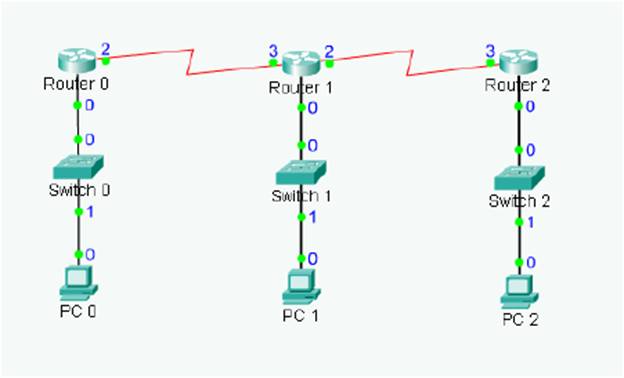
• Create a multi-router network topology
• Design an IP addressing scheme using a Class C network address and VLSM
• Apply IP addresses to the routers
• Test the topology to verify IP connectivity
Preconfigs
·
Note: The “no keepalive” command is added to
FastEthernet0/0 interface. This will
bring the interface up without having to connect a switch or a hub.
Background / Preparation
You are responsible for designing a network that
interconnects 3 geographically separated sites,
each with its own LAN. You have a class C network address
to work with and must make the best
use of the address space while minimizing wasted addresses.
To accomplish this you will develop
an IP addressing scheme using Variable Length Subnet Masks (VLSM)
to allocate IP addresses to
the LANs and WAN links in the network. You will apply the
addresses to the routers and
workstations in the simulated network and then test to
ensure that it works.
Routers simulated with Packet Tracer use RIP version 2 to
find routes to remote networks
automatically. A router advertises all networks that its
ports belong to, which is specified by the IP
address and subnet mask. RIP version 2 supports VLSM. RIP
keeps a routing table of remote
networks. The routing table associates a network (network
ID and subnet mask or network bits) to
the port on that is closest to the network. A router can
have one default port.
Step 1. Design an IP Addressing Scheme Using VLSM
Starting with the Class C network address of 192.168.1.0/24,
create subnets to allocate IP
addresses to the Ethernet LANs and WAN links in the network
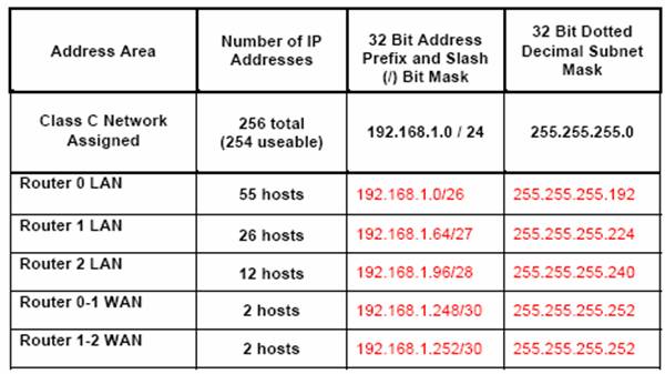
topology shown above. The design
requirements for the number of addresses are listed in the
table below. Use VLSM to minimize
wasted IP addresses. Assume ip subnet-zero is
enabled and that the first subnet (all zeros) and
last subnet (all ones) can be used.
As a general rule it is best to first allocate subnets to
the networks with the largest number of
required hosts starting from the lowest subnet number and
working up. Ethernet networks will
require more IP addresses than WAN links. Be sure to
minimize the number of addresses used on
the WAN links and allocate WAN subnets starting at the
highest subnet. Document your VLSM
subnet design using the table below. You will use these
subnet address ranges to assign interface
addresses to the routers and workstations in the scenario.
Notes:
55 hosts require at least 6 bits ~ 111111 = 63
26 hosts require at least 5 bits ~ 11111 = 31
12 hosts require at least 4 bits ~ 1111 = 15
2 hosts require at least 2 bits ~ 11 = 3
192.168.1.0/26
This means that the first two bits will be set to 00.
00000000 through 00111111 in binary
0 through 63 in decimal
192.168.1.64/27
This means that the first three bits will be set to 010.
01000000 through 01011111 in binary
64 through 95 in decimal
192.168.1.96/28
This
means that the first four bits will be set to 0110.
01100000 through 01101111 in binary
96 through 111 in decimal
192.168.1.248/30
This
means that the first six bits will be set to 111110.
11111000 through 11111011 in binary
248 through 251 in decimal
192.168.1.252/30
This
means that the first six bits will be set to 111111.
11111100 through 11111111 in binary
252 through 255 in decimal